PLCM10 Plugin Wireless Modem
The PLCM10 is an optional module
PLCM10 may be available with different configurations. Make sure what are the functions supported in the device you are using.
Warning
- Available only on Linux HMI devices that support plug-in modules
- Only one PLCM10 module per device is supported
- PLCM10 module is not supported when a WiFi dongle is already plugin in the HMI device
PLCM10 provide:
- WiFi module (requires an HMI device that supports plug-in via the USB port)
- 4G Wireless modem with a Micro-SIM slot
- GNSS module (requires an HMI device that supports plug-in via the USB port)
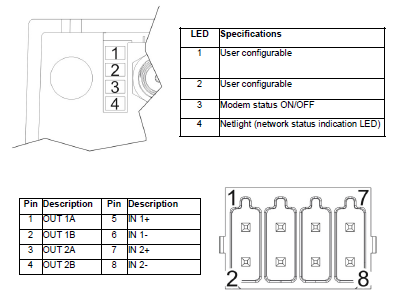
- 4 LED indicators (2 user programmable, Modem Status, Network Status)
- 2 Digital Inputs
- 2 Digital Output
Software requirements depends on BSP thread in the hosting device:
- On BSP v1.0 the version 1.0.721 or higher is required
- On BSP v1.3 the version 1.3.483 or higher is required
When the PLCM10 module is plugged and recognized, its properties will become available as “System Settings”
Wireless Network
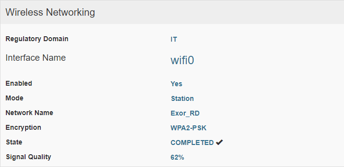
System Settings -> Network -> Wireless Network
| Parameter | Description |
|---|---|
| Regulator Domain | It is read-only information that can be set on the localization page (See "Lokalisierung") |
| Interface Name | Interface name (read-only) |
| Enable | Enable operation of Wireless Network |
| Mode |
Select:
|
| Network Name |
This is the network identifier (the SSID) When Mode = Station a "Browser" button will appear, to list the available wifi networks. When Mode = Access Point you have to define the SSID of the network you are creating. |
| Encryption |
The WPS-PSK encryption mode is supported |
| Password | Available only when the Encryption=WPS-PSK is selected. |
Once you have confirmed the system setting, you will find the connection State and the Signal Quality information.
Mobile Network
System Settings -> Network -> Mobile Network
| Parameter | Description |
|---|---|
| Enabled | Enable the Wireless Modem |
|
SIM PIN |
SIM Card PIN code if required |
| APN |
APN (Access Port Name) If you do not know this information please contact your mobile services provider. |
| Roaming | Enable Roaming option if required |
| Authentication |
Authentication mode:
|
| BAUD rate |
Baudrate (only for the HMI devices that supports plug-in via serial port):
|
| MTU/MRU |
Max Packet Size:
|
|
Username |
Username and password to be used when the authentication mode is selected |
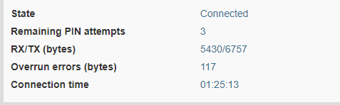
Once you have confirmed the system setting, you will find detailed information about your SIM card and mobile network connection in the Status area.
Overrun Errors
The "Overrun Errors" is a read-only parameter that is shown inside the status area only in the case of bad communication with the internal modem. In this case is advisable a review of the modem's communication parameters (Baudrate, MTU/MRU)
GNSS
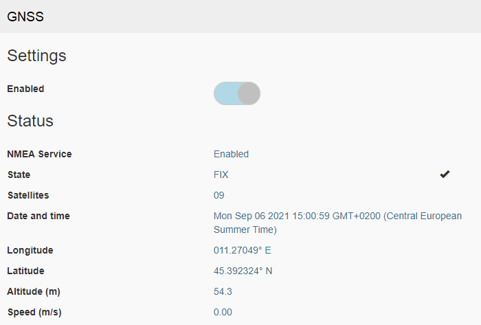
System Settings -> Network -> GNSS
| Parameter | Description |
|---|---|
| Enabled |
Enable the GNSS module Mobile Network must be enabled |
Once you have confirmed the system setting, you will find detailed information about the GNSS status value
| Status Value | Description |
|---|---|
| NMEA Service |
Enabled = the GNSS signal is present |
| Satellites | Number of locked satellites |
| State | FIX = last GNSS sentence is valid |
|
Date and Time |
Values received from the GNSS |
LEDs and Digital I/O
Behavior of the first two available LEDs and of the Digital I/O can be configured from the HMI device System Setting tool:
System Settings -> Plugins -> PLCM10
| Digital I/O | Description |
|---|---|
|
Input-1 Input-2 |
User configurable:
|
|
Output-1 Output-2 |
User configurable:
|
| LED | Description |
|---|---|
|
LED #1 LED #2 |
User configurable:
|
| LED #3 |
Show the wireless modem status:
|
| LED #4 | Show the network activity (blinking) |
System variables
All modules (Wireless Network, Mobile Network, GNSS, LEDs, and Digital I/O) can be managed from the HMI application through the tags available with the System Variables protocol.
See "PLCM10 Variablen" chapter for additional information.