Direct I/O variables
System Variables - Direct I/O protocol allows to create Tags that point to optional local I/O plugin modules.
Install and configure Direct I/O Plug-in modules
Most HMI offer 1 or 2 slots for connecting optional plug-in modules. Slot numbers are referred in the programming software for configuration of plug-in modules. Numbering of plug-in slots is shown in figure.
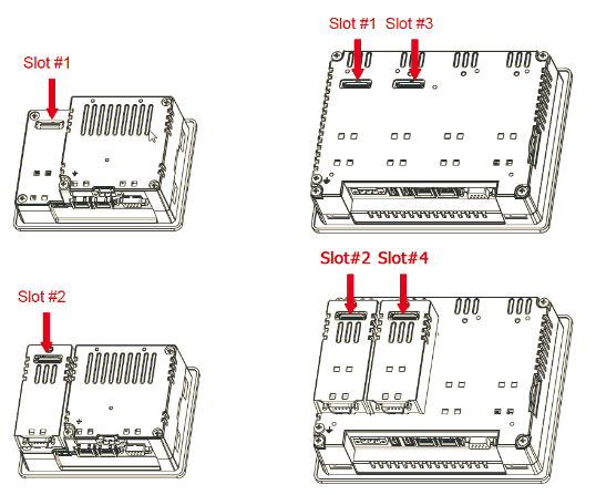
Use Plug-in List available in the System Settings menu to check if I/O plug-in modules are correctly recognized in the system and what is their slot number.
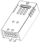
Plug-in I/O Modules details
Plug-in I/O modules have been designed for creating simple applications with a limited number of digital I/O signals.
| Module | I/O configration | Image |
|---|---|---|
|
8 Digital Inputs / |
|
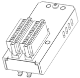 |
| 2 Relay Outputs |
|
|
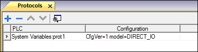
Protocol Editor Settings
From PLC Model list of Protocol Editor dialog, select Direct I/O.
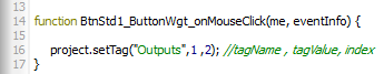
Tag Editor Settings
Path: ProjectView> Config > double-click Tags
- To add a tag, click +: a new line is added.
- Select System Variables from the Driver list: tag definition dialog is displayed.
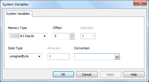
| Element | Description | ||||||||||||||||||||||||||||||||||||||||||||||||||||||||||||||
|---|---|---|---|---|---|---|---|---|---|---|---|---|---|---|---|---|---|---|---|---|---|---|---|---|---|---|---|---|---|---|---|---|---|---|---|---|---|---|---|---|---|---|---|---|---|---|---|---|---|---|---|---|---|---|---|---|---|---|---|---|---|---|---|
|
Memory Type |
Indicates the resource with this rule: <module name>#<slot number> <resource type>
|
||||||||||||||||||||||||||||||||||||||||||||||||||||||||||||||
| Offset |
|
||||||||||||||||||||||||||||||||||||||||||||||||||||||||||||||
| Data Type |
Select boolean[] data type to get all resources in a boolean array. Direct I/O Tags can be accessed with JavaScript programming. |
||||||||||||||||||||||||||||||||||||||||||||||||||||||||||||||
|
Arraysize |
In case of array Tag, this property represents the number of array elements. Note: Arraysize depends on the type of plug-in in use. In case of wrong configuration of the tag there will be no error reported, neither in HMI Logger nor in the Protocol Error Message System Variable<convert to text and insert new text here> |
||||||||||||||||||||||||||||||||||||||||||||||||||||||||||||||
|
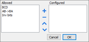
Conversion |
Conversion to be applied to the tag.
Depending on data type selected, the Allowed list shows one or more conversions, listed below.
Select the conversion and click on plus button. The selected item will be added on Configured list. If more conversions are configured, they will be applied in order (from top to bottom of Configured list). Use the arrow buttons to order the configured conversions |